Ground Profiling
Overview
SENSR-I needs to be able to distinguish ground points from other points to work properly. By default the software assumes the site's ground to be perfectly flat (with the ground level set at 0 meters). In reality, principally outdoor, sites tend to be on uneven grounds. SENSR-I provides a ground profiling tool to define which points are on the ground in an uneven setting.
Ground profiling works by dividing the detection area into a grid of equally-sized cells. The goal here is to tune the height of each cell to match with the ground profile of the environment.
caution
Before using the ground profiling feature, make sure you have aligned the LiDARs with the ground through Ground Alignment and calibrated your LiDARs.
How to Ground Profile
Step 1. Select an Algo node
- Click on the ground profiling icon:

- Select an Algo node by clicking the point cloud belonging to it. Once selected, click the "Next" button.
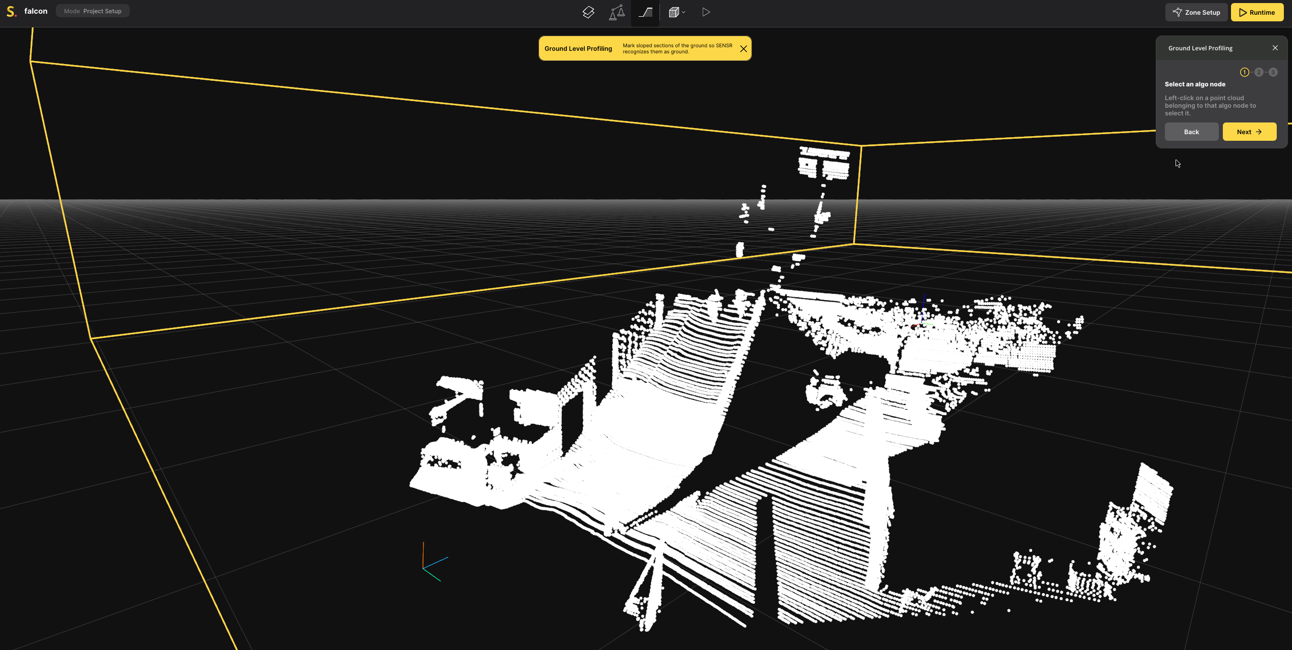
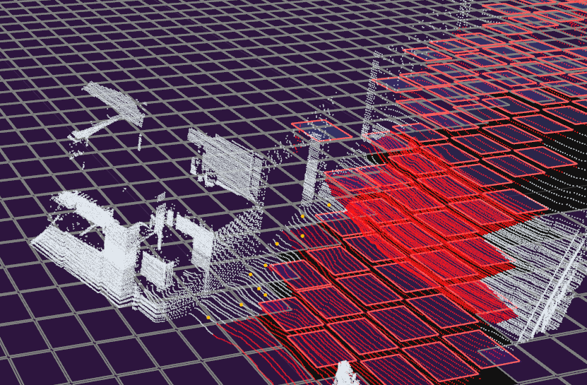
In Ground profiling mode, the points regarded as ground potint are displayed in Red while the points above ground are displayed in White.
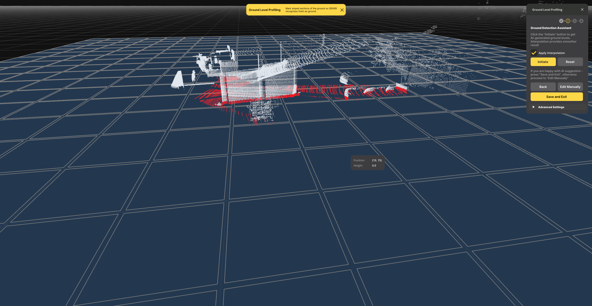
Step 2. Profile using the Assistant
To easily profile your site, SENSR is equipped with an automatic Assistant.
 Please note that the Assstant will profile sites with up to 2 meters high slopes. Beyond that, the profiling must be done manually. Manual ground profiling instructions can be found here.
- Select if Interpolation shall be applied using the tick box
Apply Interpolation - Click
Initiateto start the Assistant. - Once the ground is profiled, verify if the results are satisfactory: ground points shall be Red while other points shall be White
- If the result is satisfactory, click
Save and Exit.
The ground is now profiled and perception results will be significantly improved.
Step 3. Manual Ground profiling
In case you need the site to be specifically profiled or if your site has steep slopes, Manual Ground Profiling can be used.
To do so, after selecting the Algo Node to ground profile and in the Ground profiling window, click Edit Manually and follow the steps below:
Step 3.1. Adjust the ground level for each grid cell
There are three ways to adjust the ground level for each grid cell.
- Ground Cell Selection (default)
- Ground Point Selection
- Manual Cell Tuning
The Ground Cell Selection is sufficient for most cases, but if you require additional options, you can select an alternative method in the Advanced Settings.
Adjust the ground level of as many grid cells as necessary by following the instructions below. Once complete, click "Next" to proceed to the "Interpolation" step.
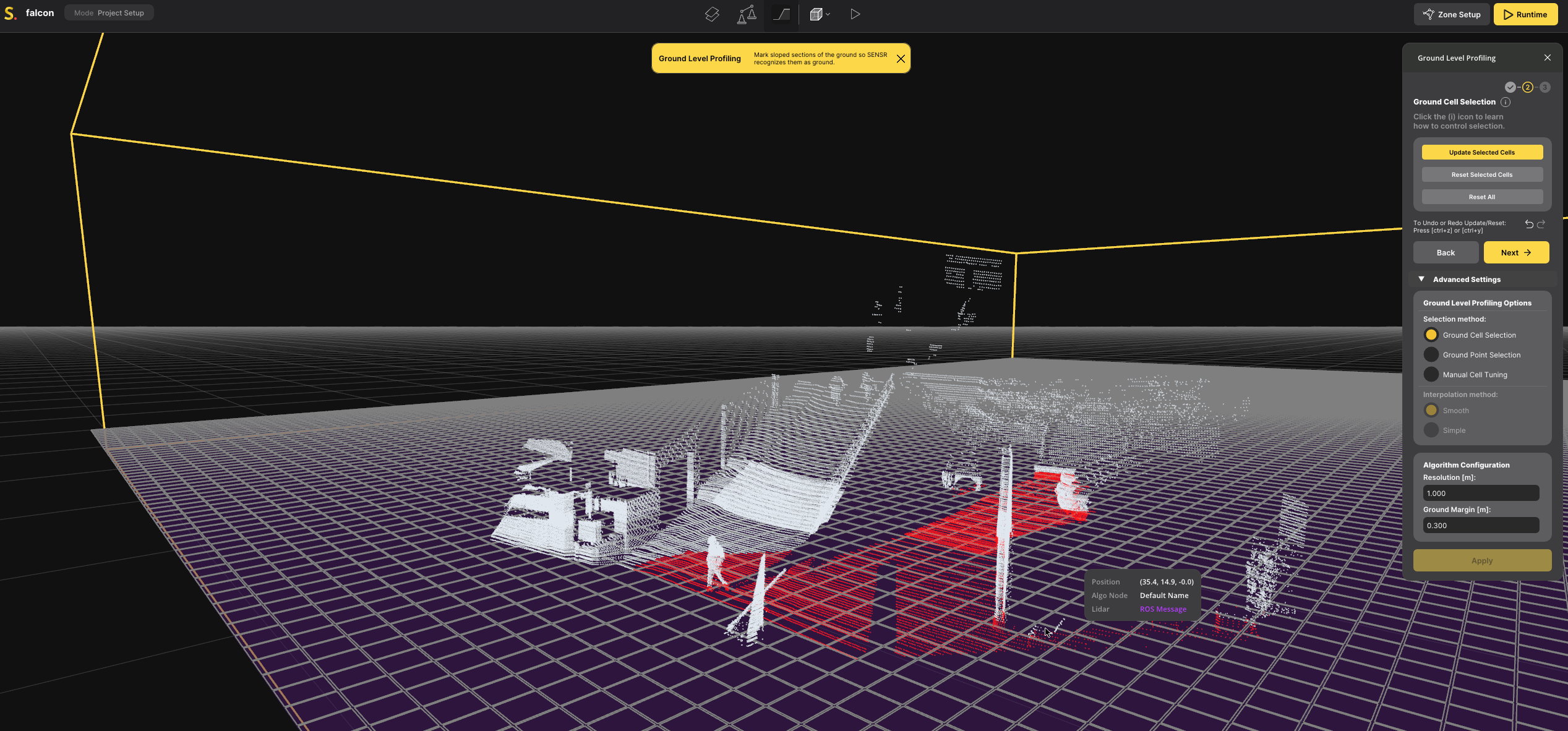
Ground Cell Selection
"Ground Cell Selection" is the default and simplest method to use. In this method, the user selects the cells to be updated, and the ground level is automatically set to the height of the highest point in that cell.
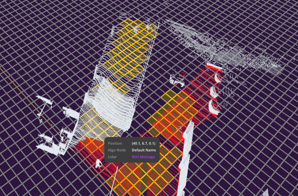
- Left-click or left-click+drag the mouse to select the grid cells containing only ground points.
- The borders of each selected grid cell will be highlighted in Orange color.
- You can deselect the grid cell by ctrl+clicking or ctrl+click+drag the mouse.
- Click the "Update Selected Cells" button.
- The borders of each updated grid cell will be highlighted in Red color.
- The ground level for each grid cell will be updated, and you can check the result by visually inspecting the cell heights. Additionally, you can confirm the results by observing the color of points: Red points are identified as underground.
- If a cell was incorrectly set you can revert it by clicking the "Reset Selected Cells" button.
- The ground level for each grid cell will be reset to 0 meters.
- You can use the "Reset All" button to reset all the updated grid cells.
Ground Point Selection
Ground Point Selection is a method for adjusting the ground level of each grid cell by selecting ground points. In this method, the ground level is set to the height of the highest point selected within that cell. This method is recommended when there are many objects or when more precise ground profiling is needed.
- Left-click or drag the mouse to select the points that should be considered as ground.
- The selected points will be highlighted in Orange color.
- You can deselect the points by ctrl+clicking or ctrl+dragging the mouse.
- Click the "Update Cells" button.
- The borders of each updated grid cell will be highlighted in Red color.
- The ground level for each grid cell will be updated and you can check the result by checking the grid cell planes are now defined higher or lower than previously depending on the points inside. You can also confirm the result by checking the color of points: Red points are defined underground.
- You can use the "Reset All" button to reset all the updated grid cells.
Manual Cell Tuning
Manual Cell Tuning is a method to adjust the ground level for each grid cell by manually entering the ground level. Use this when adjusting the ground level without any point obtained from the ground. It can be also used when the result of Interpolation is not satisfactory.
- Left-click or drag the mouse to select the grid cell.
- The borders of each selected grid cell will be highlighted in Orange color.
- You can deselect the grid cell by ctrl+clicking or ctrl+dragging the mouse.
- Put the height that you want to set as ground level in the "Ground Level" input box.
- You can refer to ground level information of each grid cell or height information of each point by hovering the mouse on the grid cell or points.
- Click the "Update Selected Cells" button.
- The borders of each updated grid cell will be highlighted in Red color.
- The ground level for each grid cell will be updated and you can verify the results by observing the changes in the grid cell planes. Additionally, you can confirm the results by observing the color of points: Red points are defined underground.
- Select the grid cells if the height of those are excessively high or adjusted wrongly from the actual ground height due to objects in the grid cell. And click the "Reset Selected Cells" button.
- The ground level for each grid cell will be reset to 0 meters.
- You can use the "Reset All" button to reset all the updated grid cells.
note
By default, the ground profiler's cell resolution is set to 5m x 5m.
In case you need a more thinly defined ground profile, the parameters Resolution and Ground Margin can be adjusted in the Advanced Settings.
Resolution
Resolution determines the size of grid cells. A finer (smaller) resolution allows for more detailed adjustment of ground profile but will require more efforts to set up.
After changing the resolution, click the "Apply" button to apply the changes.
Ground Margin
It determines the minimal distance between the cell ground level and the point at which an object is recognized. This setting can be useful for ignoring miscellaneous objects that may be close to the ground, such as those blown by the wind.
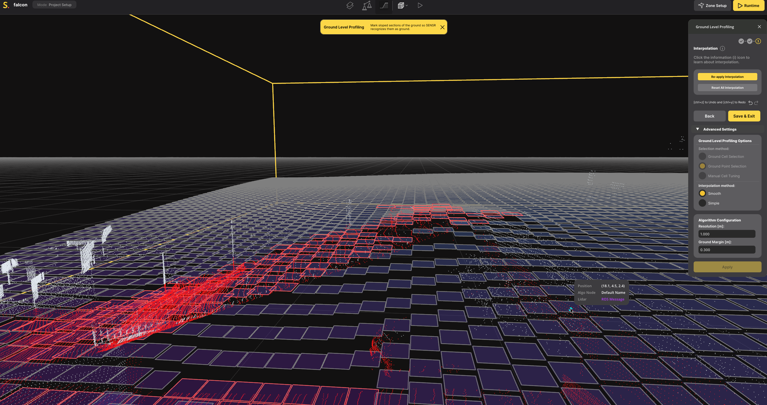
Step 3.2. Interpolation
Interpolation can be used to adjust the ground level of grid cells that were not set manually using the methods mentioned above. It reduces the effort required for Ground Profiling, as manual adjustments to the height of each grid cell are not necessary. Additionally, interpolation leads to more accurate ground profiling for areas where ground points are not visible from the LiDARs.
Two Interpolation methods are provided; Smooth and Simple. The Smooth interpolation is recommended for most cases and set as default. You can try Simple when the result of Smooth is not satisfactory. It can be changed in the Advanced Settings.
- Apply Interpolation
- Applies the interpolation for all grid cells which are not manually profiled.
- If interpolation has already been applied, and changes have been made to the ground level of any cell using any of the three methods, the button will be changed to "Re-Apply Interpolation". This button will update the interpolation result based on the changes you made.
- Reset All Interpolation
- This action will reset all the interpolated grid cells to 0 meters, effectively removing any interpolation, leaving only the manually profiled grid cells.
Step 3.3. Save the Ground Profiling Result
Once all ground points are colored in Red and points above the ground level are colored in Blue, you can consider the ground profiling complete. To finalize, click the "Save & Exit" button. The results of the ground profiling will be saved within the Algo node.
You can also see the result by observing the color of points under the ground level changing to Dark Blue color in the Runtime mode.