Calibration
Overview
SENSR utilises LiDARs to detect and track objects within the devices' field of view. This chapter will walk you through the process of setting the LiDARs up and if multiple sensors are used, calibrating them with each other in order to fuse their pointclouds. The process of setting up LiDARs with their location and orientation in the larger referential is called the Caibration process.
This chapter will walk you step-by-step through the calibration process using the sample data that is delivered with SENSR. The same principles can be used to calibrate your LiDARs on any site.
Pre-requisite
This tutorial is based on SENSR's sample data, to follow along with this tutorial, you will need to download the sample data:
- Open a terminal window (CTRL-ALT-T)
- Navigate to the folder
/opt/seoulrobotics/utils - Type:
./download_sample.sh
The script will download the sample data that will be used
Project setup
For this tutorial we will create a brand new project, run our pre-packaged sample data and calibrate the sensors.
Create the Tutorial Project
- Either in the first start screen or through the
File > New Projectmenu, create a new project. We will call it ‘tutorial’.- Leave the directory as default to ensure the rest of the tutorial matches your configuration
- Enter ‘tutorial’ as the Project name.
- Click Done
Set up Sample Replay
Click on Algo Node Settings gear icon.
- In the
Rosbagfield at the bottom of the configuration pop-up,If everything is installed in the default locations, the path will be/root/seoulrobotics/samples/sample_data.bag - Click
Confirm
- In the
Set up Sensors
Click '+ Add Sensor' to add sensors
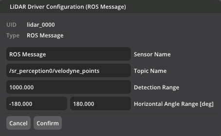
Click 'Lidar. Ros Message'. You will see Lidar Driver Configuration (ROS Message) window.
Fill in the Topic Name field. For this example, the topic name is /sr_perception0/velodyne_points
How to Find Topic Name
A ROS bag can contain a wide variety of information. SENSR only requires the LiDAR point cloud data to function. To find out what data a ROSbag contains, you can query the bag file for its contents.
Open a new terminal (CTRL-ALT-T)
Navigate to the location of the bag file.
Enter:
cd /opt/seoulrobotics/samplesEnter:
rosbag info sample_data.bag- If you get the error message: command ‘rosbag’ not found, tyinstall the python ros reader:
sudo apt install python3-rosbag
- If you get the error message: command ‘rosbag’ not found, tyinstall the python ros reader:
You should see the following:
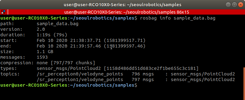
Any topic of type PointCloud2 can be used by SENSR
Click the + icon below the Sub Node
Identify the message type: in front of sensor_msgs/PointCloud2
- Give the sensor a unique name. For example ‘Sensor 1’
- Copy the *topic name* from the rosbag info into the Topic Name field.
In this example: /sr_perception0/velodyne_points
Click Confirm.
Repeat this for all PointCloud2 topics in the bag file. For this sample_data.bag, you have to add one more sensor(topic).
You should have two sensors with unique names and topics associated with them. Make sure the second sensor has the topic name: /sr_perception1/velodyne_points
Click Start Algo Nodes to start the calibration process.
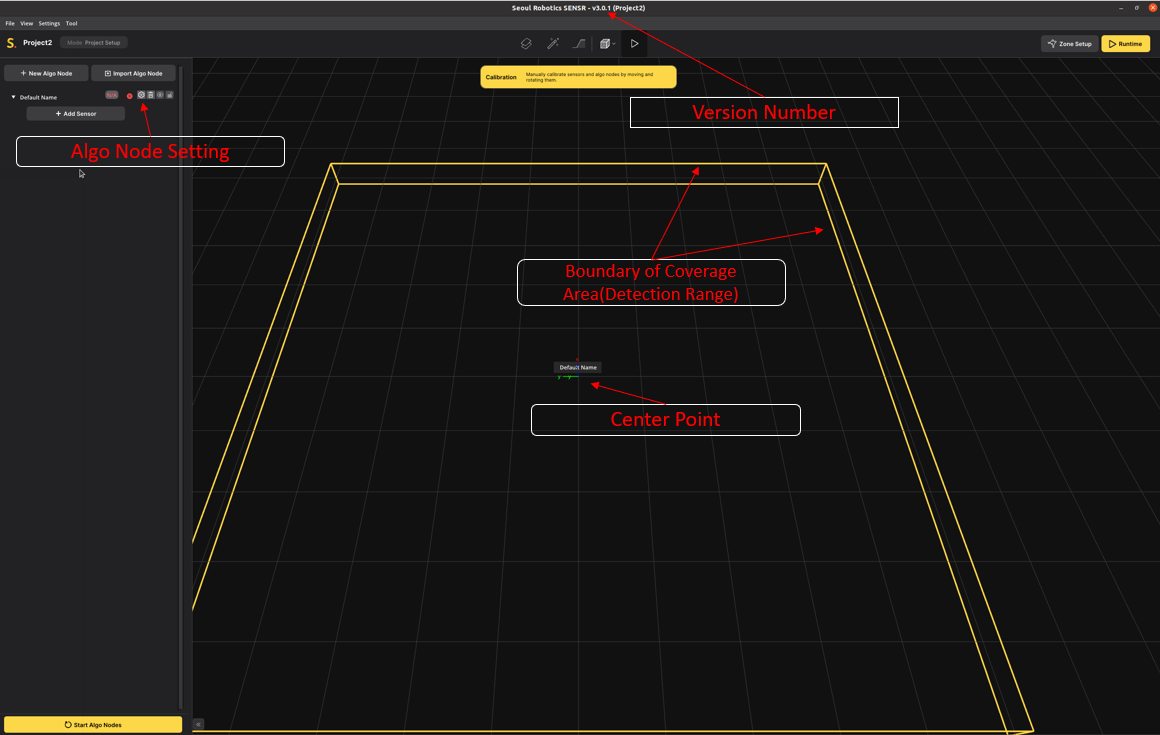
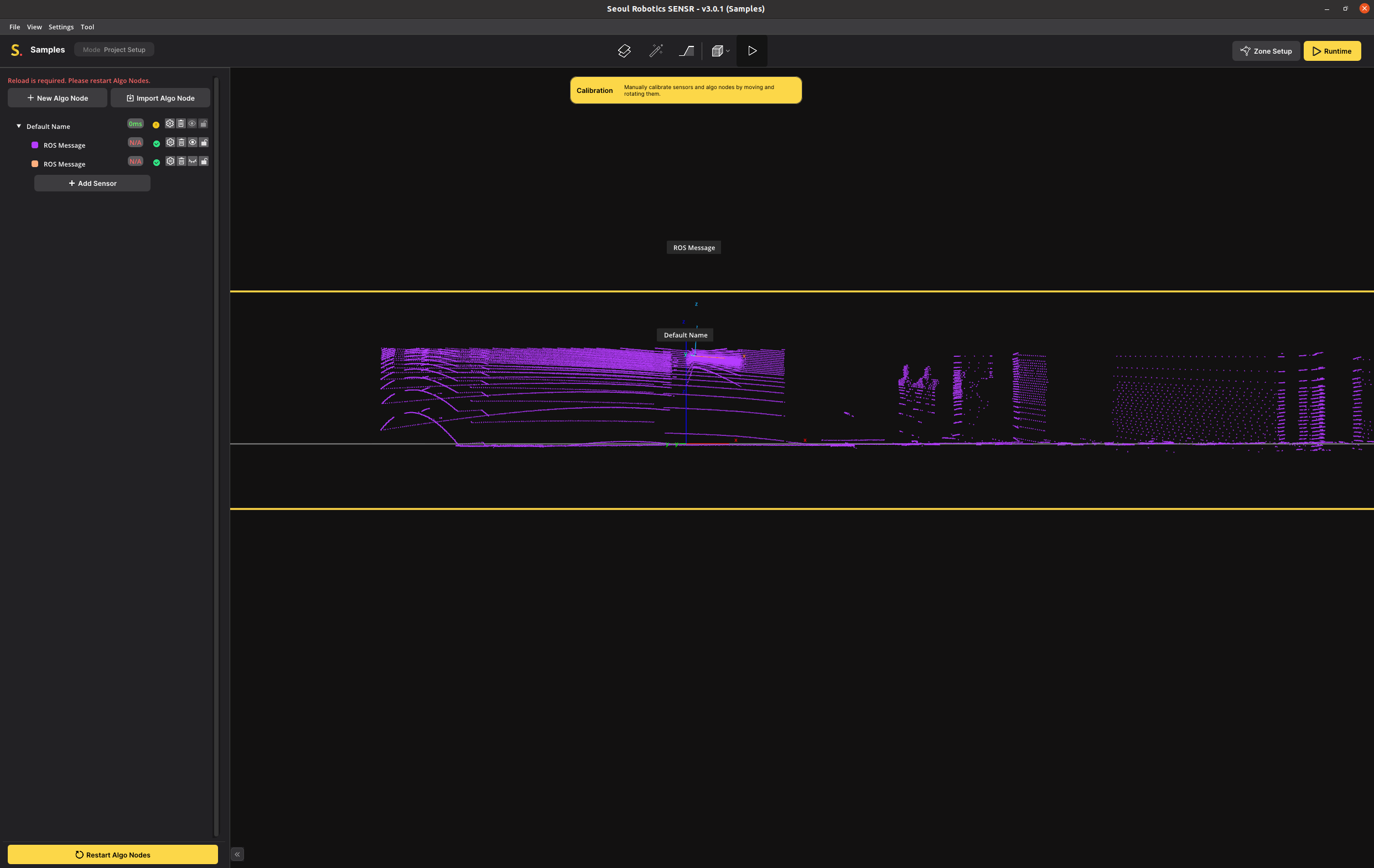
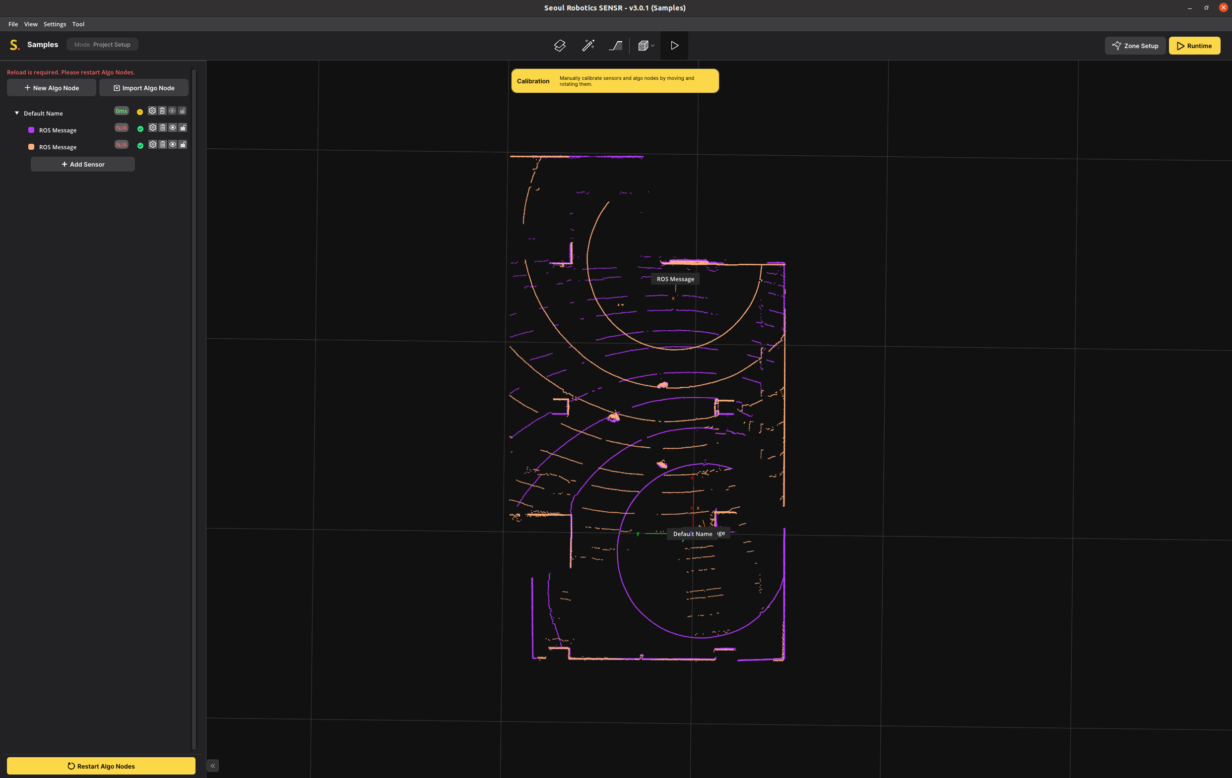
After following those instructions, you should see the following on the screen.
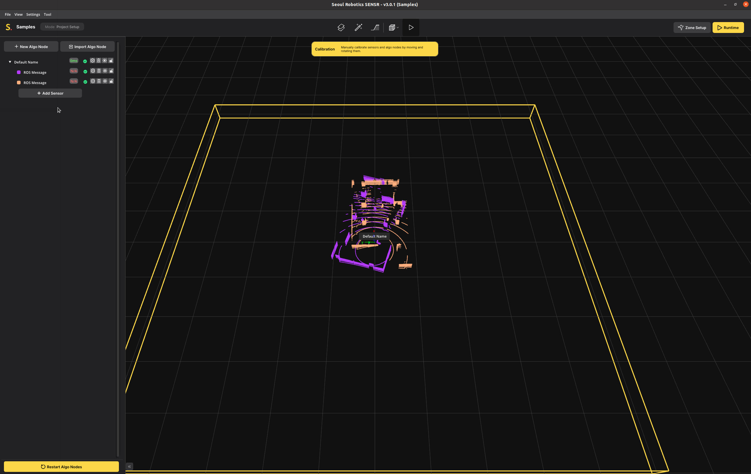
The scenario of the replay is three people walking around a room that also has a number of static pillars in it. Two sensors are placed at opposite sides of the room near the ceiling.
Calibration
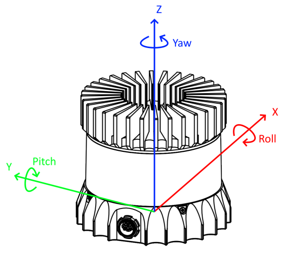
Coordinate Systems
SENSR uses a right-handed coordinate system. The ground plane aligns along the X-Y plane and Z being altitude.
There are six values that have to be solved during the calibration phase. First is the location (X, Y and Z) and second is the rotation (Pitch, Roll, Yaw).
For this tutorial, and for calibration in general the following is defined:
- Rotation around Z = Yaw
- Rotation around X = Roll
- Rotation around Y = Pitch

Start the Calibration Process
The two main goals to achieve during the calibration process are:
- Align the real ground plane with the ground plane in SENSR.
- Match each sensor's pointcloud relative to each other sensor.
Note: The perception quality highly depends on the quality of the calibration in SENSR.
Calibration can be done many different ways. This tutorial describes one of the methods that can be applied to small and large installations alike. In this tutorial we are working with only two sensors, but its principles are applicable to large sites made of 200+ sensors. At the start of a new calibration, SENSR places all sensors at the zero location (0,0,0). This can be confusing to work with, so it is recommended to start with a clean slate and calibrate sensors one at a time.
- Go to each sensor in the list and click on the eye icon. This will make each sensor invisible.
- Now make only Sensor 1 visible.
- Select Sensor 1 in the list by clicking on the name.
Now only Sensor 1 should be visible and selected. You can tell whether a sensor is actively selected by the point cloud belonging to that sensor turning white.
Before we do this:
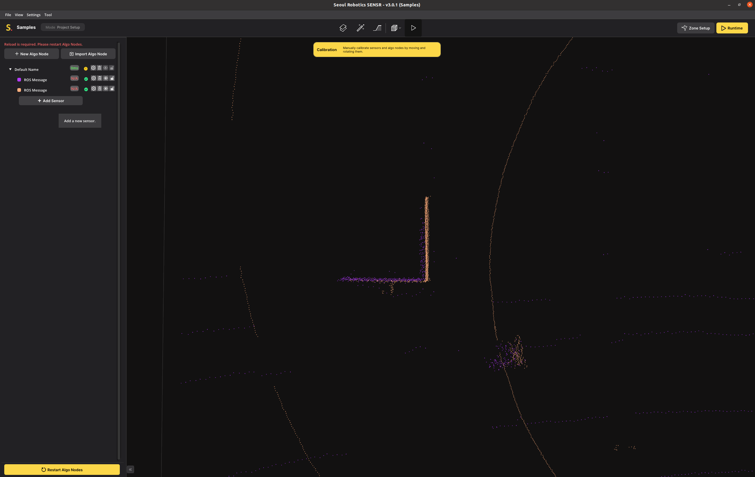
- Go to the 3D viewport, hold the right mouse button and rotate the view until the camera is level to the ground.
This is when you cannot rotate any further and the yellow rectangle turns into a line. You are now in side-view. The yellow line indicates the ground level of the SENSR world. Below this level nothing will be tracked.
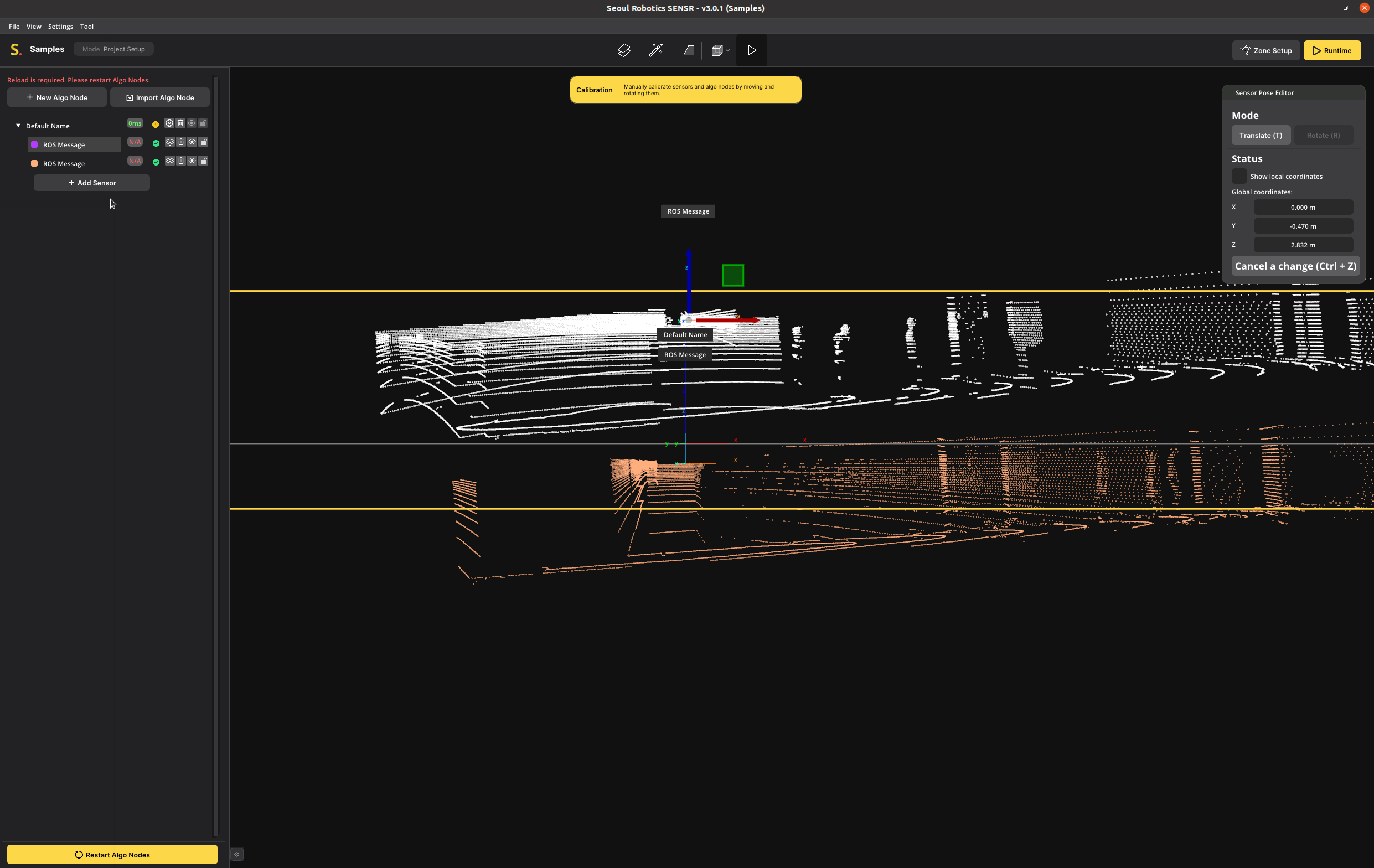
You can now clearly see that the majority of the point cloud is below ground level. This is because the Z of a new sensor is set to zero, so SENSR assumes that the lidar is on the ground.
Ground Alignment
Our first goal is to raise the Z to the actual installed height of the sensor and the ground level. The Ground Alignment tool allows to perfectly align the LiDAR's ground with the referential. It can be found in the Tool menu or by selecting a PointCloud and pressing the F4 key.
- Select the Ground Alignment icon on the Header or in the Menu bar Tool > Ground Alignment
- Select any point of your sensor to start the ground alignment for that sensor
- Click "Next"
- Rotate the point cloud to an angle where you have a good view of the ground
- Select three points that:
- You know are on ground level
- Are spread far apart
- And ideally form a wide triangle
- Compare the alignment result before and after, and Click "Apply".
- If the point cloud is upside down, click
Flipping Groundbutton to flip.
- If the point cloud is upside down, click
In this image the three yellow, green, red markers indicate the three selected points.
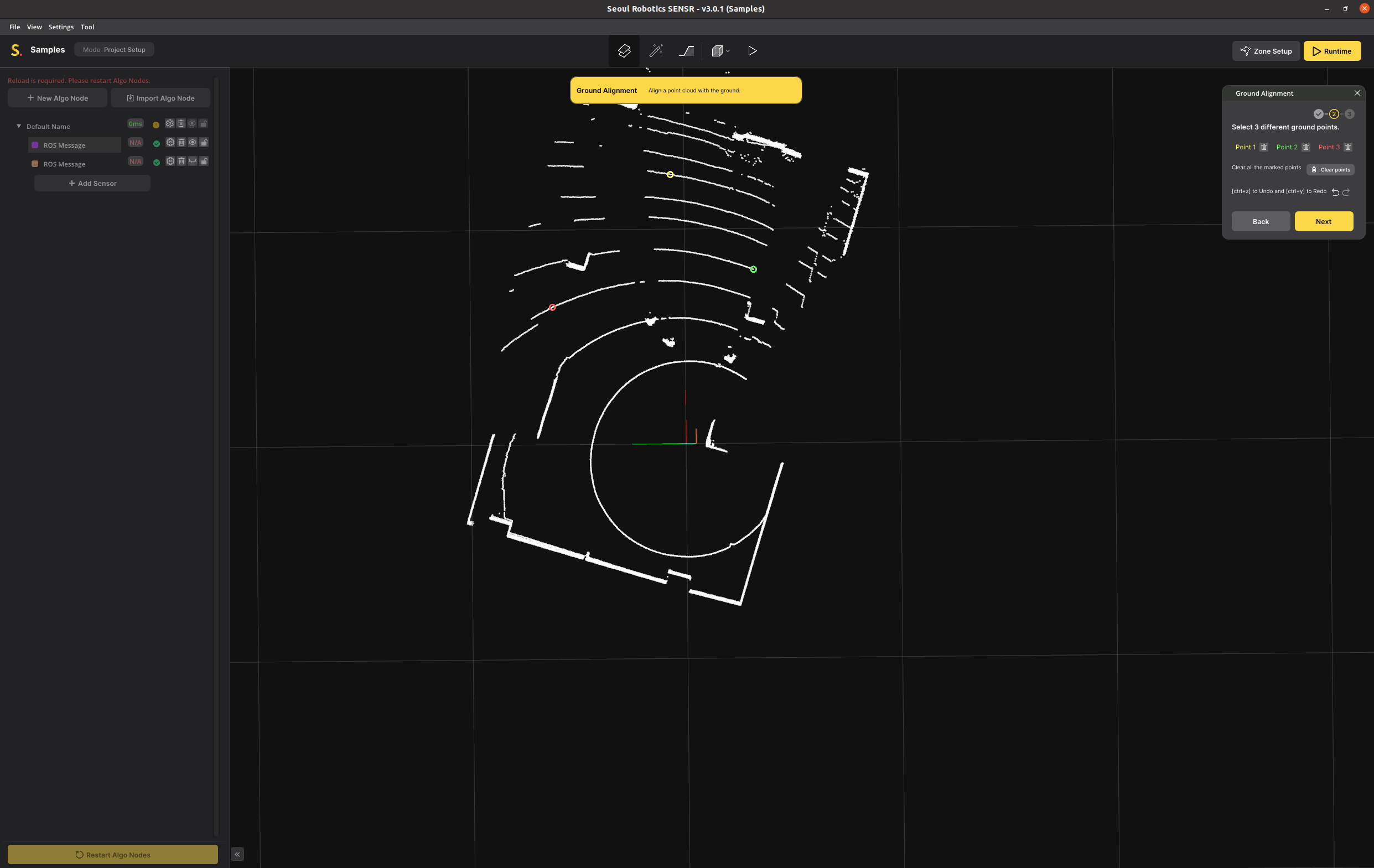 In this image the three colored markers indicate the three selected points.
- Compare the alignment result before and after, and apply.
- Note: If the point cloud is upside down, click
Flip Groundbutton to flip.
- Note: If the point cloud is upside down, click
- Click on Launch the ground alignment
The point cloud's 3 points selected earlier are now aligned with the ground plane. You can verify the the proper alignment by selecting View > Side view and make sure the points are above ground as illustrated below.
Repeat these steps for all your sensors to align everything with the ground plane as illustrated below:
Considerations for a successful ground alignment
- Identify the site's largest flat area possible for defining the ground so that all/most LiDARs can be aligned relative to it.
- In particular outdoor, it can happen that the ground is not flat, if the above method is not possible, it is then recommended to use the site's lowest point to calibrate the LiDARs against it.
- For uneven ground: hill, slope, stairway... SENSR is equipped with a ground profiling tool that allows the user to profile the site's ground according to its geometry. This step will be described further in the manual.
- When selecting 3 ground points, try to select them so that they form a triangle as large as possible on the ground plane. LiDARs sometimes generate noise or have slight inaccuracies, by selecting 3 points very close to each-other, the ground alignement may be imperfect due to that noise.
- Once all sensors have been ground aligned, to verify the alignment quality, select the ground profiling tool in the top menu ribbon and make sure that all ground points are colored red. A red point indicates a point below or within the ground plane while a white point indicates a point above the ground plane.
Moving and Rotating Sensors
Now the values Z, Pitch and Roll have been solved for both sensors. That leaves X, Y and Yaw.
To solve these, it is recommended to switch from Perspective to Top-view (Orthogonal) mode. This switches the system to a 2D top-down view and will remove the effect of perspective from the point cloud data and make it much easier to match up walls and corners.
Just like the ground alignment, it is recommended to start with the first sensor and get it aligned properly. To do this:
- Make Sensor 2 invisible
- Select Sensor 1
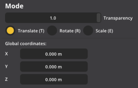
You will see a Mode box pop-up on the screen. This box allows you to move the sensor and rotate it. We are going to fix Yaw first, so select the Rotate option or use the ‘R’ keyboard shortcut
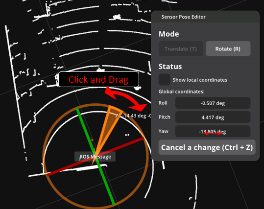
There are a couple of ways to rotate.
- You can use the 3D widget on the left and drag it.
- You can hold the mouse on the Yaw field and drag it left to right. If you hold Shift while dragging, it will rotate faster.
- You can double-click or CTRL-click on the Yaw field to enter a value manually.
- Rotate Sensor 1 so the walls line up with the grid. The Yaw value should be around the 16.5 value for this tutorial.
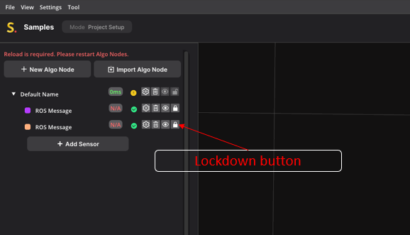
- Sensor 1 is in place. To prevent any accidental movement of Sensor 1 you can click the Lock icon next to the sensor to lock it in place.
- Now make Sensor 2 visible.
It looks like Sensor 2 is already rotated correctly, but remember that Sensor 2 is at the opposite side of the room. This means that it actually has to rotate 180 degrees to align correctly to Sensor 1.
This is why it is important to, when you have a large coverage area with many sensors, have a floorplan ready as a reference with the rough installation locations of each sensor, so you have an idea of where each sensor should be relative to the others.
- Take Sensor 2 and rotate it by 180 degrees. In this case it is fastest to double-click the Yaw field and enter the value 180.
The final step is to move Sensor 2 so all the walls and pillars match Sensor 1. To do this:
- Switch to the Translate mode or press the ‘T’ keyboard shortcut.
- Move Sensor 2 so it matches Sensor 1
You have three options to move the sensor:
- Drag the blue rectangle in the 3D widget to move the sensor along the ground without affecting the Z value
- Hold and drag the mouse in the X and Y value boxes. Hold shift to move faster.
- Double-click or CTRL-click in X and Y to enter a manual value.
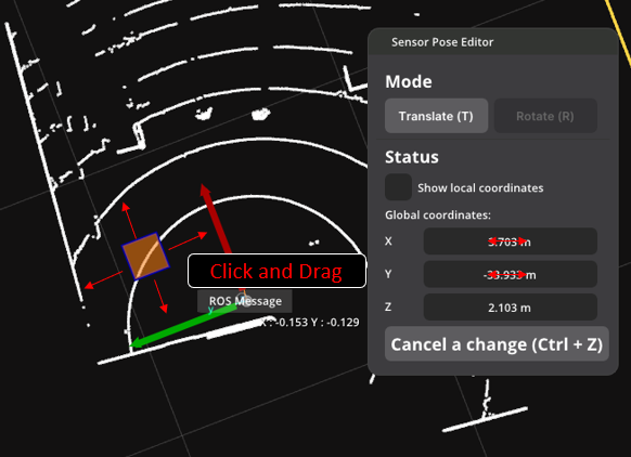
In this tutorial the X and Y value of Sensor 2 should be 13.6 and 2.0 respectively.
The final step is tweaking the location and the rotation so all walls and corners match up as close as possible. In general, for rooms like this, it is best to get the Yaw dialed in perfectly and then move the unit to the correct location. Long straight walls can be used to tweak yaw and hard corners are best to use for the final location.
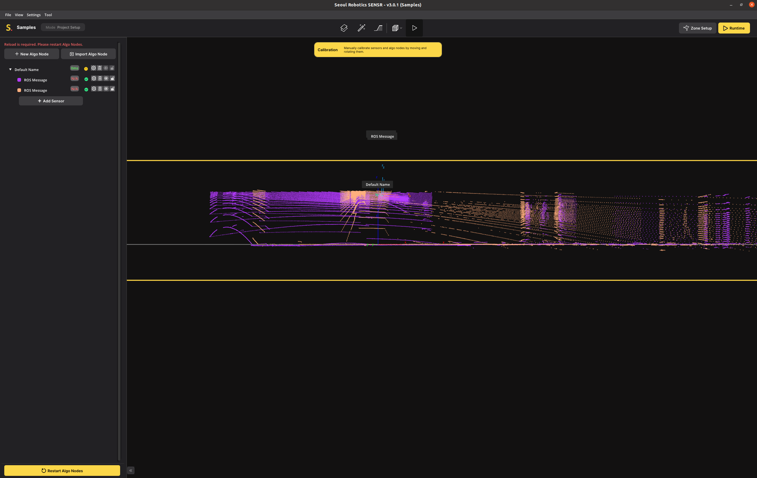
In the image below, Sensor 1 is shown in purple and Sensor 2 in orange. Once get a perfect overlap, you can lock down the calibration of these two sensors.
The calibration of Sensor 1 and Sensor 2 is now complete. If your installation has more sensors, you can make them visible one at a time and continue the calibration process.
You can switch back to perspective mode and look at the calibration from different angles to make sure everything looks correct.
Optimizing the World Size
This step is optional, but it is useful to understand how this works so you are able to optimize computing resources and maximize tracking performance.
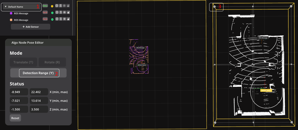
One of these Algo Node Settings is the Detection Range. This is the total world size that SENSR is processing. The default for this world size is 100x100x5 meters in space. For this tutorial dataset, we are only tracking people in a single room, so the world size is much greater than the actual observable area. We can reduce processing and memory resources by reducing the world size.
On the left is the default world size of 100x100m, on the right is the optimized world size of 20x35m, an improvement of 93%
note
Note that both Algo Nodes and Sensors have Detection Ranges. A Sensor Detection Range applies to only one sensor. The Algo Node Detection Range applies to all sensors equally.
- Click an Algo Node on the list,
- Click Detection Range on the Algo Node Pose Editor and scale the Detection Range values on the workspace or at the editor.
The calibration process is complete. The calibration will automatically be saved when you exit the application. Saving can also be done manually at any time during the calibration by pressing File > Save or using the CTRL+S hotkey.
You can now launch runtime to check the tracking results, or continue the manual and create zones first.
Tip: Background Map
You can import 2D or 3D maps at the background of SENSR world, like the video below.
Load a Background Map
- Open a window at
View > Background Map
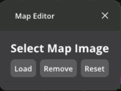
Load a background image
We support
jpegpngobjfile for the background imageCalibrate your background image with scaling, translating, and rotating